Implementation Guide
1. Introduction
The goal of the SPaT Challenge is to encourage state or local agencies throughout the United States to deploy Dedicated Short Range Communications (DSRC) broadcasts of Signal Phase and Timing (SPaT) at approximately 20 intersection locations, typically in a corridor or network setting. The intent of this document is to support agencies that have decided to deploy SPaT broadcasts by providing an overall summary of the implementation process.
This document is arranged as follows:
- Section 2: Physical Architecture Drawing and Summary of Needed Functions and Data Exchanges – This section presents an overall diagram of the primary components of a SPaT deployment, together with a summary of the functions required.
- Section 3: Overall SPaT Implementation Guidance – This section presents a high-level summary of three resources that describe a checklist of activities, specifications for SPaT hardware, and lessons learned from SPaT deployments, together with hyperlinks to the source documents.
- Section 4: Installing New Hardware/Software to Support SPaT – This section presents minimum existing infrastructure needs to support SPaT to help you determine if your existing signal control software is compatible with the SPaT broadcast. This section also provides information to help you determine the additional hardware/software needed to be implemented to support the SPaT broadcast, and finally describes the V2I Hub as a resource available to all agencies.
- Section 5: Performance Requirements for SPaT, MAP, and RTCM – This section provides performance requirements for SPaT broadcasts based on integration with the Red Light Violation Warning Application
Alternatives to DSRC SPaT Broadcasts
There is currently an approach towards disseminating traffic signal timing status to travelers that does not use DSRC broadcasts. The intent of this subsection is to recognize this alternate approach, and to clarify some functions of the DSRC approach. In areas where traffic signal controllers are connected to central signal control systems, a central system communicates regularly with some or all of the traffic signal controllers (TSCs) at the intersections. This enables operators to select to change the current signal timing plans in operation at the intersections without traveling to the intersections. This also enables individual intersections operating adaptive control to communicate their real-time status to the central controller.
Several startup companies are beginning to offer a hardware solution to agencies wishing to provide a central signal control system option for SPaT broadcast. Typically this is done using a small device that interfaces with the central signal control computer which can redistribute real-time traffic signal data to selected third parties. The connection to the central signal control computer is typically done through Ethernet ports. One port plugs into the hardware that draws the SPaT data from your central signal control computer a second port then provides for the distribution of the data to others.
Some of these companies offer installation at no cost to the agency but requiring that the central signal control system uses NTCIP compliant communications protocols and requiring a SPaT data stream via Ethernet from the central signal control computer. And they typically offer some agency control over who the data is then redistributed to. The company would also typically need to know intersection layouts and phase diagrams.
This approach potentially avoids the need to install intersection level equipment but is only viable if an agency has a centrally controlled and/or monitored signal system. There are also concerns about data rebroadcast latency, which will be dependent on both how the central control system communicates with the signals and how the installed rebroadcast hardware works. These companies may also have some prearranged data sharing agreements with other parties that may influence who you may ultimately be able to share the data with.
This section is not intended to reflect positively or negatively about either the centralized approach or the intersection based approach, but rather to explain some clarifications about the intersection based DSRC broadcast of SPaT, as follows:
- The intent of DSRC broadcast of SPaT at 5.9 GHz is to provide secure transmissions of the data with short time delays during all weather conditions. V2I Applications such as Red Light Violation Warnings (RLVWs) are described by functional requirements of SPaT broadcasts at a frequency of 10 broadcasts per second, which has been proven using DSRC. Any delay in the DSRC broadcast would be both minimal and a reliable delay that does not fluctuate.
- Operating DSRC at signalized intersections also allows for two way communications between the vehicle and the infrastructure. This may allow vehicles to communicate the lane they are traveling in to allow the signal controller to consider this as part of adaptive control. Similarly, transit or emergency vehicles may use the DSRC communications to send priority requests to the signal controllers.
- DSRC broadcasts of SPaT at the signal include lane specific details reporting the current signal phase.
- DSRC broadcast of SPaT is a one-way broadcast to all vehicles approaching, and therefore there are no privacy concerns regarding a message being sent directly to specific vehicles.
2. Physical Architecture Drawing and Summary
The intent of this section is to describe the overall actions required for a SPaT broadcast deployment to help readers understand the concept of resources presented later in this document. The operation of a DSRC broadcast of SPaT messages can be described by a series of high level actions that must occur, as follows:
SPaT Messages Output from Traffic Signal Controller. The traffic signal controller located roadside at the intersection will generate the current signal phase and timing parameters used to control the signal heads and pedestrian crossing signs. NTCIP 1202 compliant traffic signal controllers are typically capable of generating an output of the SPaT parameters as 1202 SPaT messages.
Conversion of 1202 SPaT Messages to J2735 SPaT Messages. In order for the DSRC broadcasts of SPaT messages to be compliant with the J2735 standards for V2I message exchange, the 1202 SPaT messages must be converted into J2735 formats prior to broadcast. This will ensure that vehicles operating V2I communication capabilities can interpret the message communications. Currently, the J2735 Version 2016 is the latest version.
Generation of intersection MAP data. In order for vehicles approaching an intersection to interpret the SPaT messages being broadcast, the vehicle systems must have a reference to determine the approach (or signal phase) they are following, and therefore understand the current display on the signal head. This is accomplished by the DSRC broadcast including a MAP message broadcast. The MAP message is not created in real-time, but rather is a static description of the geometries of the intersection and vectors describing approaches. The vehicle systems will compare GPS location readings on the vehicle against the MAP message and determine the vehicle’s approach.
Generation of GPS Correction data. In order for the vehicle to accurately identify the approach/phase using the MAP message, it is critical that the location of the vehicle (determined by the on-board GPS) is accurate. This can be accomplished by a broadcast of GPS correction information as standardized by the Radio Technical Commission for Maritime Services (RTCM) as a method for minimizing the effects of GPS error caused by atmospheric conditions or reduced satellite access. The general concept of RTCM is that a base station with a known location (the location may be known by either by surveying in the station location or operating a GPS receiver for a long continuous period of time) continuously receives satellite signals and determines a current latitude/longitude position given the current atmospheric conditions. The base station then compares the position determined with the current atmospheric conditions to the known location and computes a correction factor that corrects the current calculated position to the known position. This correction factor is the RTCM message that can be sent out to vehicles. Depending upon the vehicle and the GPS system on board, the vehicle may or may not be able to apply the correction factor. Creation of the RTCM message may either be done by operating a base station at the intersection, or by retrieving the RTCM from an on-line source, or by a central calculation at the TMC.
Combining SPaT, MAP, and RTCM for broadcast. The SPaT, MAP, and RTCM messages are combined and sent to the DSRC antenna for broadcast to the vehicles.
Figure 1 below illustrates a high level physical representation of the functions to be performed to accomplish real-time DSRC broadcast of SPaT messages. Actions drawn as white ovals represent those that are either performed now by traffic signal controllers (TSC) or that would be performed by TSC upgrades. Actions drawn as green ovals represent those functions that would require additional components beyond what is in typical signal control cabinets. While various approaches are possible, Section 4 of this document presents the V2I Hub (developed by FHWA) as an open source software solution with supporting reference documents to perform the needed functions for SPaT deployment.
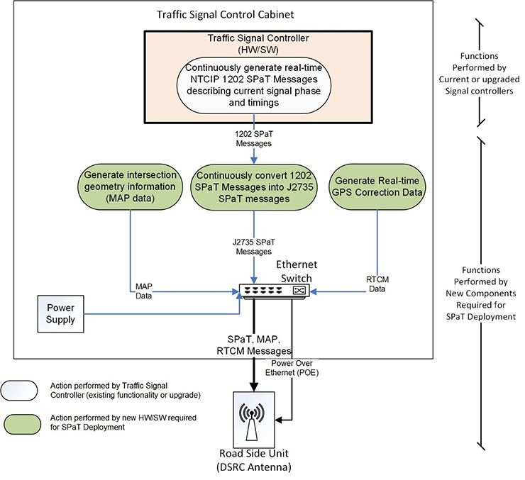 Figure 1 – Illustration of Functional Needs of SPaT Deployment
3. Overall SPaT Implementation Guidance
The intent of this section is to highlight and link to three documents that are available to support agencies and contractors as they deploy DSRC SPaT broadcasts.
Resource #1: V2I Hub Deployment Checklist & Guidance
In September 2016, FHWA completed a project that documented the process of deploying DSRC broadcasts of SPaT, MAP, and RTCM corrections. As part of this project, the project team created a checklist of common design, approval, and installation activities required to successfully complete deployment of DSRC systems.
The bulleted list below identifies the items in the checklist: The detailed checklist, together with detailed activities for each bullet can be found in the V2I Hub Deployment Checklist & Guidance[1] document.
- Project Initiation
- Jurisdiction Kickoff Meeting
- Design
- Jurisdiction Approval
- Approvals and Permits
- Order Equipment
- Software Development, Installation, and Testing
- Field Verification Prior to Installation
- Field Installation
- System Test, Inspection, and Approval
- Operations and Maintenance
Resource #2: DSRC Roadside Unit (RSU) Specifications Document
The Draft DSRC Roadside Unit (RSU) Specifications Document provides details on hardware requirements that would be used to support SPaT, including:
- Chapter 2, System Overview defines an RSU that meets all requirements of the document specifications (page 5), which would support SPaT.
- Chapter 2, System Overview provides examples of various deployment configurations (pages 7-9).
- Chapter 2, Basic Functionality details RSU functionality with a context diagram including the inputs, outputs, enablers, and controls for supporting activities, including message broadcasts (page 10).
- Chapter 3 includes RSU system requirements that would apply to the hardware/software needed to support SPaT, organized into categories:
- Power (pages 16-17);
- Environmental (pages 17-21), including consideration of local weather-related conditions;
- Physical (pages 21-22), including weight, enclosure, mounting;
- Functional (pages 22-46), including broadcasting, positioning, system and interface log files, message processing, security, and USDOT Situation Data Clearinghouse and Warehouse;
- Behavioral (pages 46-52), including operational states, modes, and configuration, and health and status monitoring;
- Performance (pages 52-54), including radio performance; and
- Interface (pages 54-66), including internal and external interfaces for DSRC, 802.11, IEEE 1609.2, IEEE 1609.3, IEEE 1609.4, and WAVE Service Advertisements.
Resource #3: CAMP Red Light Violation Warning Demonstration Lessons Learned Document
4. Installing New Hardware/Software to Support SPaT
Minimum Existing Field Equipment to Support SPaT
The following bullets describe the minimum hardware and software components that is required at the intersections where a SPaT broadcast is planned to be deployed:
- A traffic signal controller (TSC) with NTCIP 1202 SPaT message outputs via an open Ethernet port.
- An Ethernet switch in the traffic signal controller cabinet that has at least three ports available to all operate on the same subnet.
- Availability in the traffic signal controller cabinet’s interior to locate or mount equipment.
Minimum New Hardware and Software Required to Support SPaT
As noted in the illustration in Section 2, typical hardware and software components that need to be added to accomplish SPaT broadcasts include:
- Software to translate the NTCIP object oriented SPaT data into J2735 SPaT messages for broadcast;
- Creation of a MAP message to be broadcast that describes intersection geometry;
- Acquisition or creation of RTCM (GPS correction) messages for broadcast;
- The DSRC antenna providing broadcast of SPaT, MAP, RTCM; and
- Communications to link existing and new components.
The V2I Hub – A Resource for SPaT Deployment
The V2I Hub is an open source software product and series of guidance documents to support the needed SPaT, MAP, and RTCM broadcasts. As illustrated in Figure 1, there are three high level functions that need to be performed (beyond the SPaT output generated by the TSC) to assemble the needed information to be sent to the DSRC antenna (illustrated as green ovals in Figure 1). The V2I Hub offers solutions to accomplishing these functions. The following bullets and hyperlinks provide high level descriptions and links to further resources.
- The V2I Hub Software is available on the Open Source Application Development Portal (OSADP, http://www.itsforge.net/). Release notes, compilation and installation instructions, and supporting documentation are also provided on the OSADP.
- In order to broadcast MAP Messages, the V2I Hub Map Plugin requires an XML input file with the infrastructure geometry of the deployment area. Guidance for developing this file is provided in the V2I Hub MAP XML Input File Instructions (Battelle, September 2016).
- The V2I Hub SPaT Plugin requires an XML input file to convert the NTCIP 1202 SPaT messages from the traffic signal controller into SAE J2735 SPaT messages for broadcast via the RSU. Guidance for developing this Phase-to-Lane Movement (PTLM) file is provided in the V2I PTLM XML Input File Instructions (Battelle, September 2016).
- V2I Hub, RSU, and Plugin configuration guidance is provided in the V2I Hub Sample Set-Up Guide (Battelle, September 2016).
- The V2I Hub Troubleshooting Guide (Battelle, September 2016) provides information on potential issues and resolutions.
5. Performance Requirements for SPaT, MAP, RTCM
Preliminary Performance Requirements for SPaT to support Red Light Violation Warning applications are:
- SPaT broadcast at 10 Hz;
- MAP broadcast at 1 Hz.
- RTCM version 3.0 correction message type 1001 (GPS L1 Observations) at 5 Hz, and
- The message type 1005 (Antenna Reference Point (ARP) coordinates) at 2 Hz.
The Vehicle-to-Infrastructure (V2I) Safety Applications Performance Requirements, Volume 1 for Common Requirements (FHWA-JPO-16-248) and Volume 3 for RLVW (FHWA-JPO-16-250) contain performance requirements for the storage, transmission, and processing of SPaT, MAP, and RTCM messages for the issuance of RLVW notifications, alerts, and warnings.
Click here to download a PDF of the above resource - updated October 2017